During a disaster, staff need enough light to read documents and screens, continue essential work, and evacuate safely. Define which workstations must remain in service and how many hours they will operate each day. Use that schedule to select luminaires, photovoltaic (PV) generation, and battery storage. The procurement team and engineers need the same task list to compare bids and verify performance at handover.
This guide covers permanent emergency operations centers, rescue coordination stations, and temporary command sites. The procurement team can start with Sections 1, 2, 4, 7, and 9, then use Appendix A to prepare an inquiry. Engineers can use Sections 3 to 6 to set targets and size the system, followed by Sections 8 and 9 for installation and acceptance. The appendices contain the standards applicability table, a glossary, and links to the original sources.
How to use this guide. Apply the standards requirements identified in the text within their stated scope and using the editions adopted at the project location. The remaining values are design recommendations or calculation assumptions to be agreed in the design and procurement documents. Before construction, obtain a professional review against local building, electrical, fire safety, and grid connection requirements.
1 Define the operating requirements
Ask the operating department to mark the workstations, map tables, equipment operating positions, circulation routes, and outdoor work areas that must remain in use during a disaster. Describe what users need to accomplish in each area so that suppliers design to the same scope.
Define the operating scope. Distinguish areas used in normal operations from those retained during a disaster. If only essential workstations are to be served, state their locations and number. Account separately for servers, communications equipment, display walls, air conditioning, and other nonlighting loads.
Set two separate durations. Specify how long command operations must continue after a power outage and how long emergency escape lighting must support evacuation. Record these as separate requirements. This guide uses 72 hours for the operational autonomy example and 3 hours as an escape lighting duration to assess for the project. Neither is a universal minimum. Section 4 explains the emergency escape lighting standards and their conditions of application.
Define the daily operating schedule. A requirement for three days of autonomy must state the daily lighting hours, the output setting for each group of luminaires, and which workstations are continuously occupied. Operating for 24 hours a day requires a different storage capacity from operating for only a few hours each day.
Set interruption and recharge limits. For workstations that cannot tolerate even a moment of darkness, specify a testable supply continuity requirement. Also state when the required energy reserve must be restored after use, and the solar or external power conditions available for doing so.
Shared design inputs. Prepare a plan showing the areas and tasks, a normal and disaster operating schedule, and a register of unresolved items. For conditions not yet verified by a site survey, record the assumption, its effect on capacity or price, who will confirm it, and by when.
2 Select a system for the site
Solar lighting may use centralized PV and storage, individual solar luminaires, or a mobile system. The options below are starting points. Select the arrangement to suit the outage tasks, site conditions, and consequences of failure.
| Application | Option to assess first | Key decisions and checks |
|---|---|---|
| Permanent operations center Prolonged operation | Centralized PV and storage for essential lighting, with independent provision for emergency escape lighting | Verify sustained operation, the effects of transfer equipment failure, installation space, and maintenance access |
| Site entrances Dispersed paths and assembly points | Standalone solar luminaires or zoned supplies; add backup for critical areas as required | At each location, check shading, autonomy, and coverage after a single luminaire fails; agree on site maintenance arrangements |
| Temporary command site Mobile deployment | Mobile storage, rapidly deployed PV, temporary lighting, and backup energy | Confirm deployment time, transport, anchoring, wiring, site illuminance, and demobilization needs |
| Retrofit with an existing uninterruptible power supply (UPS) or generator | Assess integration of PV and storage with the existing system | Verify existing capacity, interfaces, transfer arrangements, and protection; list new equipment and equipment to be retained |
At a permanent center, PV and storage can be the main energy supply for lighting during continued operations. Provide a second source based on the risk of prolonged poor weather, array damage, and constraints on resupply. A conventional grid-connected PV system normally shuts down when utility power fails. Supplying loads during an outage requires equipment designed for islanded operation. Require a transfer scheme and an on-site test of independent operation after utility disconnection. [10][13][13a]
A standalone solar luminaire can serve a specific location. Assess solar exposure, light coverage, and maintenance access separately at every location. A product’s claimed autonomy in cloudy or rainy weather does not demonstrate uninterrupted supply to the entire operations center. Temporary sites must also meet the applicable emergency escape lighting and electrical safety requirements.
Control costs in the right order. First define the areas and operating hours to be retained during a disaster. Then refine light distribution and controls by area before comparing storage, backup energy, and maintenance options. Every occupied workstation must still meet its task lighting target. Quotations should state the scope of equipment, design and installation, commissioning and training, and ongoing maintenance.
3 Set lighting requirements by task
3.1 Define the visual tasks
The procurement team can describe tasks in practical terms: reading documents, distinguishing fine map lines, reading equipment labels, or seeing stair treads. Engineers then define the assessment planes and lighting targets. Assess desktops, vertical maps, cabinet panels, and floors separately. Refer to ISO/CIE 8995-1:2025 for indoor workplace lighting and ISO 11064-6:2005 for the control room environment. Use the appropriate outdoor standards for outdoor safety tasks. [1][2][8]
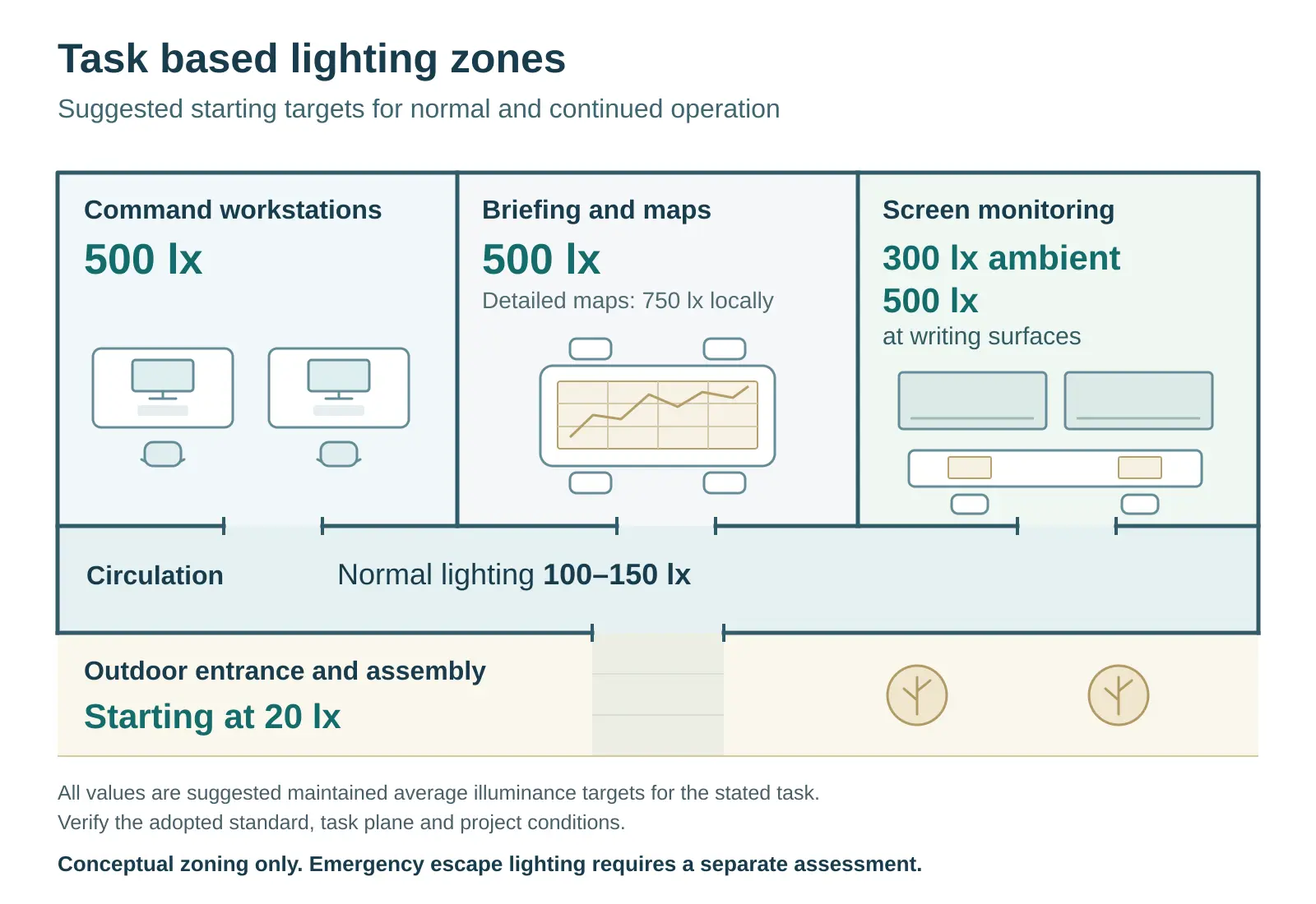
| Area or task | Suggested design target | Procurement and design checks |
|---|---|---|
| Command workstations Document and data processing | 500 lx; U₀ ≥ 0.60 UGR ≤ 19; Ra ≥ 80 | Calculate on the actual desktops; check the darkest points, screen reflections, and viewing directions |
| Detailed maps and drawings | Local lighting 750 lx; U₀ ≥ 0.70 UGR ≤ 16; Ra ≥ 80 | Confirm the detailed task category; consider Ra ≥ 90 where color codes must be distinguished |
| Briefing and meeting tables | 500 lx; U₀ ≥ 0.60 UGR ≤ 19; Ra ≥ 80 | Use separate settings for reading and presentations; check vertical illuminance on faces for video meetings |
| Screen monitoring | Start at 300 lx ambient Provide 500 lx for writing | Check with the actual screens and seating layout; avoid bright reflections and dark areas |
| Equipment rooms and cabinet aisles | Start at 200 lx in aisles Add light to panels as reading tasks require | Check vertical labels, working surfaces with doors open, and shadows during maintenance |
| General corridors and stairs | Normal lighting 100 to 150 lx | Check floors and stair treads; assess emergency escape lighting separately |
| Outdoor entrances and assembly points | Start at 20 lx; adjust for risk | Check that obstacles and faces are recognizable; assess camera needs and adjacent dark areas |
| Inventory checks and loading or unloading | Start at 100 lx; add light for detailed tasks | Check shipping labels, vehicle glare, and pedestrian and vehicle crossing points |
The table sets out this guide’s suggested starting points; it does not reproduce any one standard. Detailed design must check the actual task category, surrounding areas, and adopted standard. Unless stated otherwise, the values are maintained average illuminance on the agreed reference plane. Neither a single spot reading nor luminaire wattage is sufficient to establish compliance.
3.2 Verify lighting performance
Illuminance and uniformity. Illuminance measures light incident on the task surface, in lux (lx). U₀ is the ratio of minimum to average illuminance. The procurement team should request calculations showing the assessment grid. Engineers should check both the average and the darkest points so that bright centers do not conceal poorly lit edges.
Glare and reflections. The unified glare rating (UGR) describes discomfort glare for a particular layout and viewing condition. A luminaire data sheet stating UGR < 19 provides selection guidance; verify performance through calculations for the actual room and luminaire layout. Check screen reflections against the positions of displays, windows, and seats.
Color rendering and color temperature. Ra is the general color rendering index. Use Ra ≥ 80 as a starting point for command workstations; consider 90 for detailed color-coded tasks. Assess a color temperature of 3500 to 4000 K, then select the value using the actual screens, materials, and user evaluation. These are selection recommendations, not universally mandatory values.
3.3 Check initial and maintained illuminance
Maintained illuminance is the level to be sustained under the agreed maintenance conditions. Base the maintenance factor on light output depreciation, dirt accumulation, and the cleaning and replacement plan. A factor of 0.80 is a project assumption that needs supporting evidence. [14]
For example, a fixed-output system without constant-illuminance compensation needs an initial design average of at least 625 lx to maintain 500 lx with a maintenance factor of 0.80. State the initial acceptance value, maintenance plan, and long-term target in the procurement documents. Where constant-illuminance control is used, specify the output available throughout the maintenance cycle.
Einitial ≥ 500 / 0.80 = 625 lx
At a minimum, luminaire submissions should include photometric files for the exact model, actual input power, light output in normal and emergency modes, dimming data, and the applicable safety assessment documents. The procurement team may specify PstLM ≤ 1.0 and SVM ≤ 0.4 as quality targets for flicker and stroboscopic effects. Require supporting test results and verify performance at the main dimming settings and on backup power. These additional conditions are project requirements, not universal legal thresholds for all solar luminaires. [7][7a][20][21]
4 Provide for continued operation and evacuation
Workstations that remain in use during a power outage must continue to meet the lighting targets for the tasks being performed. Emergency escape lighting supports safe evacuation and any necessary high-risk operations. Define the circuits, operating modes, and power provisions for each function separately. ISO/CIE 8995-1 refers emergency lighting to ISO 30061. [1][3]
The following uses EN 1838:2024 as a European technical reference. State the adopted standards framework in the procurement documents, then have the engineer check all applicable provisions. Do not selectively combine assessment areas, response times, or durations from different standards systems. [5]
| Application | Key reference requirements |
|---|---|
| Escape routes | At least 1 lx at floor level in the defined assessment area. For widths > 2 m, exclude a 0.5 m perimeter strip; for widths ≤ 2 m, exclude 1/4 of the route width on each side. |
| Open areas Anti-panic lighting | At least 0.5 lx at floor level in the unobstructed core area, excluding a 0.5 m perimeter strip. |
| Both categories above | Reach 50% within 5 s and full illuminance within 60 s. Basic duration at least 1 h; minimum/maximum illuminance ratio at least 1:40. |
| High risk tasks | At least 10% of the maintained illuminance required for the normal task, and never below 15 lx. Provide full illuminance continuously or within 0.5 s, for the duration of the hazard. Minimum/maximum illuminance ratio at least 1:10. |
| Safety equipment and signs | Provide 5 lx vertical illuminance at the specified first aid, firefighting, and other safety equipment. Externally illuminated signs: 5 lx. Internally illuminated signs: luminance at least 2 cd/m². |
The minimum/maximum ratios here differ from U₀ in Section 3. Provide full coverage of stairs, changes of direction, final exits, and the routes to a place of safety. Check single-luminaire failure, glare, signs, and visibility against the standard. [5]
Preserve escape lighting during extended operations. An informative annex to EN 50172:2024 recommends 3 h for premises that are not evacuated immediately after a power failure. Determine the final duration from local requirements and the risk assessment. Keep emergency escape lighting effective while lighting for continued operations runs on backup power, and ensure safe evacuation remains possible after that backup supply fails. [5][6]
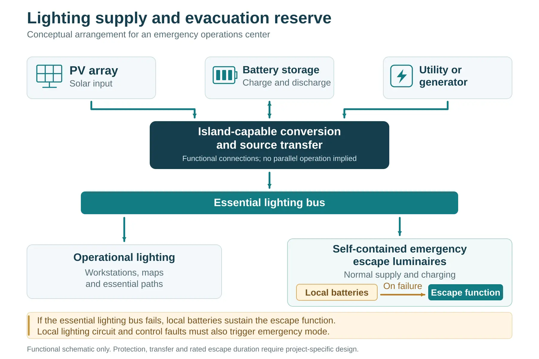
Options include a backup bus that maintains the normal supply and necessary charging for compliant self-contained emergency escape luminaires, or a suitable central safety power supply. Where energy is shared, demonstrate that general loads cannot deplete the protected emergency reserve. The engineer must also address emergency mode activation for relevant lighting circuit and control failures; testing only loss of power at the main utility supply is insufficient. [6]
Require the supplier to provide a system diagram showing which source supplies emergency escape lighting during a prolonged outage, which source remains available after the final supply for work lighting fails, and which faults trigger emergency mode. Use this diagram and the corresponding test records as the basis for technical review.
5 Design workflow
Use the same operating assumptions for the lighting layout, energy calculations, and controls. The workflow below is recommended; each step should provide the information needed by the next design discipline.
Step 1 Define operating conditions and scope
Confirm with the owner how the center will operate under normal conditions, during a power outage, at a low state of charge (SOC), and during evacuation. Agree on the areas to remain in service, operating durations, allowable interruption times, design temperatures, and minimum pre-event reserve.
Deliverables: A plan identifying tasks by area, an operating scenario table, a critical load list, and an open issues register.
Step 2 Set lighting criteria and layout
Select the applicable standards, reference planes, and calculation grids. Use photometric data for the specified luminaire models to calculate illuminance, uniformity, glare, and any required vertical illuminance. Check both initial and maintained illuminance using the maintenance model.
Deliverables: A table of lighting criteria, a luminaire layout, calculation reports for each operating mode, and a luminaire schedule.
Step 3 Build the load profile
For each operating mode, enter the luminaire quantities, actual input power, dimming settings, and operating periods in the load schedule. Include controls, inverter standby consumption, thermal management for the storage system, and recharging of emergency batteries.
Deliverables: An editable load profile and daily energy totals.
Step 4 Check storage capacity and reserve recovery
Calculate the energy available at the load for the period without usable generation, allowing for capacity at end of life, temperature, and the available SOC window. Use site weather data and charging limits to check continued operation and reserve recovery.
Deliverables: Capacity calculations, hourly SOC results, scenarios with unmet load, and the proposed response for each.
Step 5 Coordinate system and installation design
Complete the design of power transfer, protection, emergency reserves, local controls, and equipment interfaces. Check structural requirements, flood protection, fire safety, and maintenance clearances.
Deliverables: System and circuit diagrams, a control narrative, installation drawings, and a responsibility and interface matrix.
Step 6 Complete integrated commissioning and acceptance
Verify the installed luminaire layout, normal and emergency operating modes, off-grid operation, autonomy, and reserve recovery as described in Section 9. Resolve any deviations.
Deliverables: Test records, corrective action and retest records, as-built documentation, and training records.
Keep the calculations coordinated: Update the lighting and energy calculations together after any luminaire replacement, addition of workstations, or change in dimming. For constant illuminance control, also check the input power toward the end of the maintenance cycle when calculating autonomy. Do not use only the consumption of new luminaires operating at reduced output.
Use the lumen method for preliminary sizing, then use point-by-point calculations to verify the actual layout. In the equation, N is the number of luminaires; Em is the average maintained illuminance; A is the calculation area; Φ is the initial luminous flux of each luminaire in the selected mode; UF is the utilization factor for the same area and reference plane; and MF is the maintenance factor. Round N up to the next whole number. This equation alone does not demonstrate compliance with glare or uniformity requirements. [14]
N ≥ (Em × A) / (Φ × UF × MF)
6 Autonomy and reserve recovery
Battery capacity determines how long the system can operate without usable generation. PV capacity also determines how quickly the depleted reserve can be restored. The example below uses a lighting load of about 20 kWh per day. All inputs are illustrative. Actual sizing should use the project’s site, luminaire, weather, temperature, and equipment data. Unlisted loads, such as servers, communications equipment, and air conditioning, are excluded.
6.1 Daily energy demand
| Lighting and related loads | Power | Hours per day | Daily energy |
|---|---|---|---|
| Command workstations | 480 W | 24 h | 11.52 kWh |
| Meeting and map areas | 160 W | 12 h | 1.92 kWh |
| Circulation areas | 80 W | 24 h | 1.92 kWh |
| Essential outdoor lighting | 240 W | 12 h | 2.88 kWh |
| Safety signs and controls on normal supply | 40 W | 24 h | 0.96 kWh |
| Equivalent auxiliary load for the inverter, battery management system (BMS), and other equipment | 30 W | 24 h | 0.72 kWh |
| Total | 1.03 kW equivalent simultaneous load | Operating periods above | 19.92 kWh |
Ed = Σ(Pi × ti) / 1000
In the equation, P is input power in watts and t is operating time in hours; the result is in kWh. Use 20 kWh per day for the remaining calculations. Use the actual input power of the luminaires and equipment. Express all consumption as equivalent energy at the load. Do not double-count standby or auxiliary consumption already listed separately. Apply efficiency factors only to conversion losses not already included. Calculate actual AC and DC circuits separately before combining their totals.
The 30 W auxiliary load is illustrative only. It does not represent the actual thermal management and standby consumption of the storage cabinet sized below. Account separately for the energy needed to recharge batteries in the independent escape lighting system after discharge; the 40 W allowance for normal supply does not automatically cover this recharge.
6.2 Storage capacity
Assume 3 days without usable generation. The pre-event SOC is 90% and the minimum permitted SOC is 10%, giving a usable SOC window of 0.80. Use a capacity factor of 0.80 at end of life, a capacity factor of 0.90 at the minimum design temperature, and an efficiency of 0.90 for the remaining path from storage to the load. Replace the temperature and capacity assumptions with actual equipment data. [19]
Cnom ≥ (Ed × D) / (ΔSOC × fEOL × fT × ηout)
Cnom ≥ (20 × 3) / (0.80 × 0.80 × 0.90 × 0.90) = 115.74 kWh
A nominal capacity of 120 kWh is a preliminary candidate under these assumptions. After derating, the energy available at the load is about 62.21 kWh, giving about 3.11 days of autonomy. Procurement comparisons should compare energy available at the load under the same temperature, stage of service life, and SOC, rather than nominal capacity alone. If the manufacturer already guarantees usable energy under these conditions, do not apply the same derating factors again.
A workstation used 24 hours a day needs 72 hours of lighting over 3 days, which can require substantial battery capacity. If the budget is limited, review which areas must remain in service during a disaster and for how long, then recalculate the capacity. Each additional 100 W of continuous auxiliary load adds 2.4 kWh per day. Under these example conditions, 3 days of autonomy requires about 13.89 kWh of additional nominal storage.
The pre-event SOC of 90% is an operating requirement for this autonomy estimate. If routine operation to reduce energy costs discharges the battery below that level, the same autonomy cannot be claimed. Verify the independent escape lighting system’s rated capacity and duration separately, including its illuminance at the end of the rated duration.
6.3 PV capacity for operation and reserve recovery
For a conservative simplification, assume that all energy passes through storage. Use plane-of-array peak sun hours H of 3.0 h/day for a month with low solar availability, a derating factor KPV of 0.80 from the array to the charger input, a charging efficiency of 0.95, and an efficiency of 0.90 from storage to the load. KPV does not include either of these efficiencies. Peak sun hours are an equivalent energy measure, not the number of hours when the sun is visible.
PPV,day ≥ 20 / (3.0 × 0.80 × 0.95 × 0.90) = 9.75 kWp
An array of about 10 kWp only approaches daily energy balance under these solar conditions. If 3 days without usable generation deplete 60 kWh of the reserve, expressed as energy delivered to the load, the PV capacity needed to restore it over the next 3 days while maintaining operation is:
PPV,rec ≥ (20 + 60/3) / (3.0 × 0.80 × 0.95 × 0.90) = 19.49 kWp
A preliminary choice is therefore an array of about 20 kWp. The recovery estimate requires the assumed solar input and sufficient charging power. Prolonged cloudy or rainy weather, shading, and current limiting affect recovery time. Use monthly averages for preliminary sizing only; check consecutive periods of low irradiance and hourly SOC in the final design. [18]
Check power ratings separately: The equivalent 1.03 kW load does not determine the required inverter and charger ratings. Check LED driver inrush current, power factor, temperature derating, PV interfaces, maximum power point tracking (MPPT) limits, and battery charging limits. An undersized charging path will prevent the 20 kWp array from meeting the reserve recovery target.
Buyers should ask suppliers for three separate answers: how long the system can operate under the specified conditions; how much energy it can deliver to the load; and the conditions and time needed to restore the depleted reserve. The 20 kWh/day, 120 kWh, and 20 kWp figures form one set of results under these example assumptions. Do not use them as a standard configuration based only on building floor area.
7 Compare quotations on the same basis
7.1 Give every supplier the same information
The quotation request should include the project location and drawings, tasks in each area, operating hours during normal and emergency operation, lighting and autonomy targets, allowable interruption time, existing power sources, and available installation area. Include design conditions such as high and low temperatures, flooding, and wind. Appendix A provides a form to complete. Mark missing information as subject to a site survey, and require suppliers to state their assumptions and the effects on their proposals.
Require all suppliers to use the same loads and operating conditions. Prices cannot be compared directly if one proposal covers only essential workstations and another covers the whole building, or if one assumes new batteries at room temperature while another includes performance at the end of service life and in cold conditions.
7.2 Compare performance and the full scope of supply
| Item | Evidence to request | If information is incomplete |
|---|---|---|
| Lighting performance | Calculations using the same floor plan, mounting heights, task planes, and maintenance conditions | Obtain the luminaire layout and measurement points before comparing technical proposals |
| Autonomy and storage | Energy available at the load under the same demand profile, initial SOC, temperature, and stage of battery life | Recalculate on the same basis and state auxiliary energy use |
| Recharging and reserve recovery | Weather data source, energy deficit, ongoing load, charging limits, and target SOC | Request a reserve recovery calculation; PV wattage alone is insufficient |
| Faults and evacuation | System diagrams, emergency reserve, source transfer arrangements, and operation without network connectivity | Specify test scenarios and identify the areas that remain lit after each fault |
| Installation and commissioning | Itemized scope for supports and foundations, distribution, wiring, grounding, modifications, commissioning, and training | List inclusions and exclusions for each item |
| Maintenance and warranties | Cleaning and testing, battery replacement, spare parts, site service, and performance guarantee terms | Compare itemized costs and identify who is responsible and how compliance will be assessed |
Prices should be broken down into equipment, design and construction, commissioning and training, spare parts, and maintenance services. Compare future costs over the same evaluation period and with the same replacement assumptions, and list any items that have not been priced. State product defect warranties separately from guarantees for capacity, light output, and other performance. A warranty period alone does not define all of these obligations.
7.3 Six questions for the review meeting
- Where will the specified illuminance be measured? Is it the initial value at installation or maintained illuminance under the agreed maintenance conditions?
- Which luminaires, output levels, and daily operating hours does the autonomy claim cover? Does it account for aging, low temperatures, and auxiliary energy use?
- After an extended period of operation, if the last available source of operating power fails, what will continue to supply the emergency escape lighting?
- Which areas remain lit if network connectivity, a lighting branch circuit, or a power conversion device fails? How will this be verified on site?
- After the reserve has been used, under what weather conditions and at what charging power can it be restored?
- Do the equipment models to be supplied match the reports and calculations? What work is excluded from the price, and who must correct any failure to meet the requirements?
Supplier answers should be supported by drawings, calculations, equipment data, test plans, or specific project terms. Record missing information as a technical clarification item and set a deadline for its submission.
8 Assign responsibilities for integration and disaster protection
Assign one party to coordinate the complete system and its integrated commissioning. The owner confirms operational needs. The lighting team is responsible for lighting performance; the electrical and storage teams for energy supply, source transfer, and protection; and the structural and fire safety teams for safety within their disciplines. Suppliers provide data for the specified models, and installers work to approved drawings. Assign responsibility for each interface issue and record how it is resolved.
Power and controls. Verify off-grid operation, black start, recovery from low battery charge, connection of backup sources, and safe reconnection to the grid. Local control, manual operation, and necessary alarms should remain available without network connectivity. Normal occupancy sensing or energy-saving controls must not inadvertently turn off protected emergency escape lighting circuits.
Structures and site conditions. Check supports, roof connections, equipment anchorage, temporary lighting poles, and protection for cables crossing roads against local wind, snow, seismic, and flood conditions. PV module type tests do not establish the disaster resistance of the complete installation or guarantee its actual service life. [15][15a][15b][22a]
Water and flood protection. IP65 or IP66 can be a starting point for evaluating outdoor luminaires; confirm suitability for the actual exposure. An IP rating does not establish resistance to prolonged immersion. Locate storage equipment, inverters, and critical distribution equipment outside areas subject to inundation under the design flood conditions. Address drainage and water entry through conduits. Isolate flooded equipment first, then determine the appropriate action through a qualified assessment. [22]
Storage and electrical protection. Check capacity and charge and discharge limits at the design temperatures, including energy used for temperature control. Coordinate grounding, isolation, surge protection, and fault protection. Check evidence of industrial lithium battery product compliance separately from stationary installation safety and any applicable safety requirements for the complete system. [10][11][12][12a][16]
Before construction, provide: the approved equipment schedule, luminaire layouts and circuit drawings, system and control descriptions, structural installation documents, and assigned responsibilities for integrated commissioning. The relevant designers should review any equipment substitution, change in mounting height, circuit modification, or change to control settings.
9 Verify the system through acceptance testing
9.1 Set test conditions and acceptance criteria
Agree on test methods and acceptance criteria during technical review. Record initial SOC, temperature, actual power draw, dimming settings, and weather conditions or controlled inputs so that the results can be interpreted. The table below is a suggested framework for project acceptance. All tests required by the applicable standards should still be completed.
| Item to verify | Tests and evidence | Acceptance criteria |
|---|---|---|
| Operational lighting | Measurement point plan, instrument details, reference planes, operating scenes, average and minimum illuminance, and checks for screen reflections | Approved initial and maintained illuminance design; applicable uniformity and glare requirements |
| Emergency lighting | Fault response and startup; performance throughout and at the end of the full rated duration; sign visibility | Adopted standards and rated duration; verify the specified service-life conditions for both light sources and batteries |
| Continued command operations | Operating records at the specified load, SOC and temperature trends, controlled tests, and validated models | Agreed initial stored energy, load, duration without effective generation, temperature, and stage of service life |
| Reserve recovery | Solar irradiance or controlled input, charging power, load during recovery, energy restored, and target SOC | Agreed energy resource conditions, recovery time, and charging limits |
| Faults and network loss | Records of main supply, relevant branch circuit, and control faults; network loss; and local and manual operation | Agreed interruption limits, fault isolation, and continued lighting in critical areas |
| Installed system matches the design | Check installed models, quantities, locations, circuits, and settings against the calculations, item by item | Deviations reviewed; noncompliant items corrected and retested |
A brief power interruption can verify only some system functions; it cannot demonstrate autonomy over several days. A successful discharge test on a new battery also cannot, by itself, demonstrate performance throughout its service life. Verify the agreed conditions at the end of service life and at the design temperatures using guaranteed equipment data together with validated models. The emergency lighting system should meet the applicable requirements throughout its full rated duration. [5][6]
For the grid-connected PV portion, documentation and inspections can be organized using IEC 62446-1 where it applies. Keep separate records for storage, off-grid operation, and emergency lighting. Final handover should include as-built drawings, editable load schedules, the basis for the calculations, test records, an equipment register, spare parts, replacement criteria, and staff training. [17]
9.2 Maintenance and changes that require recalculation
When EN 50172:2024 is adopted, check the status of the central safety power supply daily, carry out the relevant functional and monitoring checks monthly, verify the rated duration annually, and add illuminance measurements every five years. Follow any stricter local requirements for test frequency. Schedule duration tests during periods of low risk, and allow time to recharge or provide temporary backup. [6]
For the PV and storage system, also check cleanliness, shading, support fasteners, connectors, cables, alarms, usable capacity, and energy used for temperature control. During disaster warnings, maintain the reserve specified in the response plan. After a disaster, inspect structural and electrical conditions, isolate and address damaged components, and then restore power. [22][22a]
Recheck the original autonomy commitment whenever workstations or equipment are added, lighting hours are extended, luminaires or dimming controls are changed, storage temperature-control loads increase, array shading changes, batteries are replaced, or usable capacity falls. The operations team should be able to use the delivered load schedule to identify changes that need a designer’s review.
Appendix A Quotation request form
The procurement team, end users, and designers should complete this form together. For items not yet confirmed, enter “Subject to site survey” and require suppliers to state their assumptions and the effects on configuration, delivery time, and price. The blanks are for project requirements; they do not represent default values from a standard.
Project and site
Project name, country, and city: ________________________
Facility type and drawings attached: permanent emergency operations center / campus / temporary site / retrofit
Available PV installation area and shading information: ______________
Design temperatures and principal disaster hazards: ______________
Lighting and operations
Areas and workstations to remain in use during a disaster: ______________
Task illuminance and operating hours for each area: ______________
Required operating time without effective PV generation: ______; allowable interruption: ______
Emergency escape lighting standard and rated duration: ______________
Reserve recovery target and permitted external energy sources: ______________
Other loads to be supplied and limits of the supply scope: ______________
Supply and delivery
Existing utility supply, generator, UPS, and distribution details: ______________
Scope and responsibilities for design, installation, commissioning, and training: __________
Schedule, spare parts, site service, and maintenance requirements: ______________
Items awaiting confirmation and responsible parties: ______________
Suggested performance requirements for the quotation request: Submit lighting and power supply proposals based on the same floor plan, tasks in each area, and operating hours. For the autonomy claim, state the loads, dimming levels, initial and minimum SOC, temperature, service-life conditions, and auxiliary energy use. For reserve recovery, state the energy to be replenished, ongoing loads, weather conditions, and charging power. The quotation should define the scope of design, construction, and maintenance, and include calculations, supporting documents, and an integrated acceptance test plan that match the actual configuration.
Appendix B Terms and standards
Key terms
| Term | What it means for the procurement team | What engineers need to check |
|---|---|---|
| Illuminance (lx) | How much light reaches a specified desk, floor, or task surface | State the reference plane, whether the value is an average or minimum, and whether it is initial or maintained illuminance |
| U₀ and UGR | How evenly light is distributed and whether the layout is likely to cause glare | Evaluate for the installation and viewing conditions; state the emergency lighting minimum-to-maximum ratio separately |
| Ra and K | Color rendering and color temperature, respectively | Match them to the visual task; they do not replace illuminance and light distribution requirements |
| kW and kWh | kW measures power. kWh measures energy; a 1 kW load running for one hour uses 1 kWh. | Use power to check equipment capability and energy to check operating duration |
| kWp | Nominal peak PV power under specified test conditions | This is not constant output throughout the day; calculate energy generation using weather data and losses |
| SOC | The percentage of charge remaining in the battery | State initial and minimum SOC, the reserve strategy, and the capacity assumptions |
| MF and autonomy | MF accounts for maintenance effects; autonomy is operating time without the external energy supply defined in the design | State the maintenance plan, load, and solar input assumptions so that values are compared on the same basis |
Standards by design task
The design team should confirm local requirements and the standards framework to be adopted, then match the standards below to the relevant design tasks. The editions listed here were checked on 9 November 2026. Confirm locally adopted editions and applicable amendments before procurement.
| Design task | Main references and scope |
|---|---|
| Indoor areas and control rooms | ISO/CIE 8995-1:2025; ISO 11064-6:2005; EN 12464-1:2021 where the European framework is used. [1][2][4] |
| Emergency lighting and evacuation | ISO 30061:2007 / CIE S 020/E:2007; European references EN 1838:2024 and EN 50172:2024; ISO 7010:2019 and applicable amendments for safety signs. [3][3a][5][6][9] |
| Luminaires and visual quality | IEC 60598-1:2024 used together with IEC 60598-2-22:2021; IEC 62471-7:2023 and relevant updates, where applicable. [7][7a][21] |
| Outdoor areas and maintenance factors | ISO/CIE 8995-3:2018; ISO/CIE TS 22012:2019. [8][14] |
| PV installations and arrays | IEC 60364-7-712:2025; IEC 62548-1:2023+AMD1:2025. The latter does not replace design work for storage and power distribution to loads. [10][11] |
| PV modules and acceptance | IEC 61215-1:2021 and technology-specific parts; IEC 61730-1/-2:2023; IEC 62446-1:2016+AMD1:2018 for applicable grid-connected PV handover and acceptance. [15][15a][15b][17] |
| Batteries and energy storage systems | IEC 62619:2022; IEC 62485-5:2020; IEC 62933-5-2:2025 safety requirements for grid-connected electrochemical energy storage systems, where applicable. [12][12a][16] |
References
The links below lead to the original sources for checking editions, scope, and methods. The engineering guidance and worked example do not replace the full standards.
[1] ISO/CIE 8995-1:2025: Indoor workplace lighting. Source
[2] ISO 11064-6:2005: Environmental requirements for control centers. Source
[3] ISO 30061:2007: Emergency lighting. Source
[3a] CIE S 020/E:2007: Emergency lighting overview. Source
[4] BSI EN 12464-1:2021: Current edition page. Source
[5] BS EN 1838:2024: Full text distributed by the LIA with permission; see Clauses 4–7. Source
[6] BS EN 50172:2024: Full text distributed by the LIA with permission; see Clauses 4 and 7 and Annex A. Source
[7] IEC 60598-2-22:2021: Luminaires for emergency lighting. Source
[7a] IEC test report form (2026): Assessment of emergency luminaires with IEC 60598-1:2024. Source
[8] ISO/CIE 8995-3:2018: Safety lighting for outdoor workplaces. Source
[9] ISO 7010:2019: Safety signs and amendment listing. Source
[10] IEC 60364-7-712:2025: PV electrical installations. Source
[11] IEC 62548-1:2023+AMD1:2025: PV array design. Source
[12] IEC 62619:2022: Safety of industrial lithium batteries. Source
[12a] IEC 62485-5:2020: Safe operation of stationary lithium batteries. Source
[13] U.S. Department of Energy: Solar and Resilience Basics. Source
[13a] U.S. Department of Energy: Distributed Energy Resources and Microgrids Basics. Source
[14] ISO/CIE TS 22012:2019: Determining maintenance factors. Source
[15] IEC 61215-1:2021: PV module design qualification. Source
[15a] IEC 61730-1:2023: PV module construction safety. Source
[15b] IEC 61730-2:2023: PV module safety testing. Source
[16] IEC 62933-5-2:2025: Safety of grid-connected electrochemical energy storage systems. Source
[17] IEC 62446-1:2016+AMD1:2018: Documentation and acceptance of grid-connected PV systems. Source
[18] NASA POWER: Solar Storage Systems; solar energy deficits over consecutive days. Source
[19] SAM battery storage model: Temperature and usable capacity. Source
[20] Consolidated text of EU Regulation 2019/2020, Annex II, Table 4: Scope and flicker metrics. Source
[21] IEC 62471-7:2023: Photobiological safety of visible-light sources and luminaires. Source
[22] U.S. Department of Energy: Flood protection for PV systems. Source
[22a] U.S. Department of Energy: PV system design for extreme weather. Source