This article summarizes essential formulas commonly used in solar street light design, integrating national standards and practical case studies from various papers:
1. Average Road Illuminance Calculation
Formula:
Eavg = (N × Φ × U × K) / A
- Parameter Description:
- N: Number of fixtures
- Φ: Total luminous flux per lamp (lm)
- U: Utilization factor (0.4-0.6)
- K: Maintenance factor (0.7-0.8)
- A: Road area (m2) = Road width × Lamp spacing
Example:
6m wide road, lamp spacing 30m, using 10,000 lm LED, one-sided lighting:
Eavg ≈ (1 × 10,000 × 0.5 × 0.75) / (6 × 30) ≈ 20.8 lx
2. Solar Panel Power Calculation
Formula:
Ppv = Qday / (Hpeak × ηsys)
- Parameter Description:
- Qday = PLED × Twork (Daily energy consumption, Wh)
- Hpeak: Local annual average peak sunlight hours (check meteorological data, e.g., Beijing 4.5h)
- ηsys: System efficiency (0.6-0.75, including line losses, controller losses)
Example:
Load power 80W, daily operation 10h, Shanghai Hpeak=3.8h:
Ppv ≈ (80 × 10) / (3.8 × 0.65) ≈ 324 W
3. Battery Capacity Calculation
Formula:
C = (Qday × D) / (DOD × ηbat × Vsys)
- Parameter Description:
- D: Number of consecutive cloudy days (usually 3-5 days)
- DOD: Depth of discharge (0.5 for lead-acid batteries, 0.8 for lithium batteries)
- ηbat: Charge/discharge efficiency (0.85-0.95)
- Vsys: System voltage (12V/24V)
Example:
Daily consumption 800Wh, 24V system, 3 days backup, lithium battery:
C ≈ (800 × 3) / (0.8 × 0.9 × 24) ≈ 138.9 Ah → Choose 150Ah battery
4. Solar Panel Installation Angle
Formula:
θ = φ + (5° to 15°)
- Parameter Description:
- φ: Local geographical latitude
- Winter optimization: latitude +10°~15°, summer optimization: latitude -5°
Example:
Nanjing latitude 32°, fixed bracket tilt angle set at 37° (32°+5°) to improve winter power generation.
5. Wind Pressure on Solar Panels
Formula:
F = 0.61 × v2 × A
- Parameter Description:
- v: Maximum wind speed (m/s)
- A: Wind-facing area of the photovoltaic panel (m2)
Example:
Panel area 2m2, design wind speed 30m/s:
F = 0.61 × (30)2 × 2 = 1098 N
Need to verify the wind resistance of the lamp pole and foundation.
6. Component Operating Voltage Correction (Temperature Effect)
Formula:
Vmp = Vmp(STC) × [1 + α × (T – 25)]
- Parameter Description:
- α: Temperature coefficient (approximately -0.35%/°C for monocrystalline silicon)
- T: Actual operating temperature (°C)
Example:
Nominal component voltage 18V, operating temperature 60°:
Vmp ≈ 18 × [1 – 0.0035 × (60-25)] ≈ 15.3 V
7. Voltage Drop Compensation Due to Temperature
Formula:
ΔV = Nseries × α × ΔT × Vmp(STC)
Example:
3 series-connected components, each Vmp=30V, temperature difference 35°:
ΔV ≈ 3 × (-0.0035) × 35 × 30 ≈ -11V
Need to adjust the MPPT voltage range.
8. Solar Panel Capacity Optimization Design
Empirical Formula:
Ppv(opt) = 1.2 × Ppv
- Consider shadowing, dust loss (efficiency reduction of 10-20%)
- When paralleling multiple components, increase bypass diodes to reduce hotspot effects.
9. Typical Design Parameter Comparison Table
| Parameter | Reference Value | Standard Basis |
|---|---|---|
| Illuminance uniformity U0 | ≥0.4 (main road) | CJJ45-2015 Road Lighting Standards |
| Component tilt angle error | ≤±3° | GB/T 9535 Photovoltaic Module Standards |
| Battery cycle life | ≥1500 times (lithium battery) | GB/T 22473 Energy Storage Standards |
| Wind resistance rating | ≥12 levels (33m/s) | GB 50009 Building Load Code |
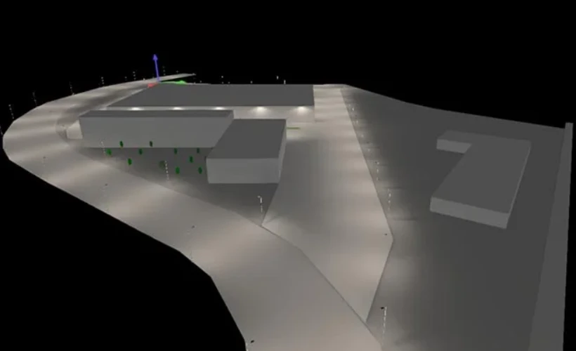
Note: Actual design should be combined with PVsyst simulations and DIALux lighting simulations, and validated through field tests.