1. Solar airport lighting Brightness Selection Standards
1. Illumination (Lux) Requirements
| Area Type | International Standard Illuminance Range | Uniformity (Uo) |
|---|---|---|
| Departure/Arrival Halls | 150-300 lx | ≥0.4 |
| Taxiway | 50-100 lx | ≥0.6 |
| Runway Edges | 20-50 lx | ≥0.7 |
| Stair/Step Areas | 200-300 lx | ≥0.5 |
| Baggage Sorting Area | 300-500 lx | ≥0.6 |
Basis: FAA AC 150/5345-7E and CIE 115:2010 recommendations, glare should be avoided (Threshold Increment TI ≤ 15%).
2. Luminous Flux (Lumens) and Luminous Efficiency
- Light Source Selection: LED fixtures with luminous efficacy ≥ 150 lm/W (solar systems should prioritize high efficiency with low consumption).
- Luminous Flux Calculation: Based on area size and target illuminance, formula: Total Lumens = Area (m²) × Target Illuminance (lx) ÷ Maintenance Factor (0.7-0.8).
2. Color Temperature and Color Rendering Index
1. Color Temperature (CCT)
- Taxiway/Runway: 5000-6000K (cool white light with high contrast for obstacle recognition).
- Terminal Building Interior: 4000K neutral white (balancing comfort and visual clarity).
- Rest Areas/Passages: 3000K warm white light (reducing visual fatigue).
2. Color Rendering Index (CRI)
- Security Check Area/ID Verification Area: Ra ≥ 90 (accurately restoring color details).
- Other Areas: Ra ≥ 80 (meeting basic color rendering needs).

3. Pole Height and Material Design
1. Pole Height
| Area Width | Recommended Pole Height | Installation Spacing |
|---|---|---|
| Taxiway (30-60m wide) | 12-18m | 30-50m (symmetrical lighting) |
| Terminal Perimeter Road | 8-12m | 20-30m |
| Pedestrian Path/Stairs | 4-6m | 10-15m |
2. Material Selection
- Pole: Hot-dip galvanized steel (corrosion resistant) or aluminum alloy (lightweight, wind load resistant ≥ 40m/s).
- Solar Bracket: Anodized aluminum + stainless steel bolts (suitable for high humidity environments).
4. System Design and Continuous Operation
1. Solar Power Supply System
- Continuous Lighting Days: At least 5 days (backup for rainy weather), equipped with lithium iron batteries (cycle life ≥ 5000 times).
- Component Power: Calculated based on daily charging efficiency ≥ 20%, formula: Solar Panel Power = Daily Consumption (kWh) ÷ (Peak Sunlight Hours × 0.8).
2. Intelligent Control Optimization
- Automatic Dimming: Through light sensors + microwave radar sensing, full power during peak human flow, reduced to 30% during idle periods.
- Remote Monitoring: Integrated KNX/EIB protocol (reference FAA case), supports fault alarm and energy consumption analysis.
5. Solar airport lighting Cost and Return on Investment (ROI)
| Project | Cost Composition | Payback Period |
|---|---|---|
| Initial Investment | Fixtures + Poles + Solar System: $200-$400/set | 3-5 years |
| Operation and Maintenance Costs | Annual maintenance fee <$50/set (LED lifespan 100,000 hours) | |
| Energy-saving Benefits | 70%-90% energy savings compared to traditional grid systems |
Note: According to IEA data, airport lighting accounts for 15%-20% of total energy consumption, and intelligent control can further reduce electricity costs by 30%.
6. System Optimization Recommendations
- Glare Prevention Design: Use cut-off fixtures (beam angle ≤ 60°) to avoid affecting pilots’ visibility.
- Redundant Configuration: Set up dual circuits for key areas (such as runways) to ensure system reliability.
- Maintenance Convenience: Modular fixture design that supports quick replacement (reference IEC TS 62100 cable standards).
References
- FAA AC 150/5345-7E “Airport Lighting Circuit Standards”
- CIE 115:2010 “Road Lighting Performance Standards”
- IEC TS 62100 “Airport Lighting Cable Technical Standards”
For specific parameter calculation tools or case details, further region size and environmental data can be provided. For any inquiries or assistance, please contact Luxman Solar Street Light Manufacturer.
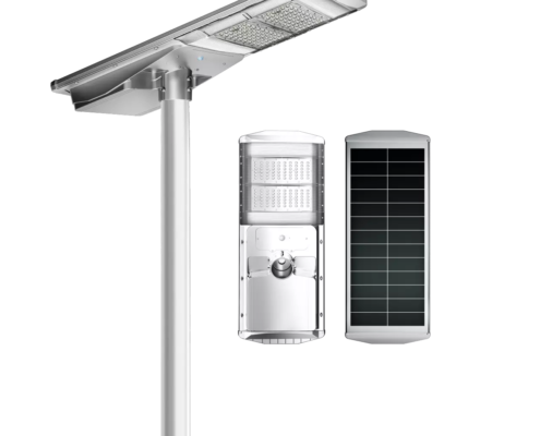
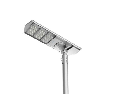
Airport Solar street light