Solar prison perimeter lighting Guidelines
As a professional streetlight manufacturer with 20 years of experience in outdoor special venue lighting design, Luxman has formulated this […]
As a professional streetlight manufacturer with 20 years of experience in outdoor special venue lighting design, Luxman has formulated this […]
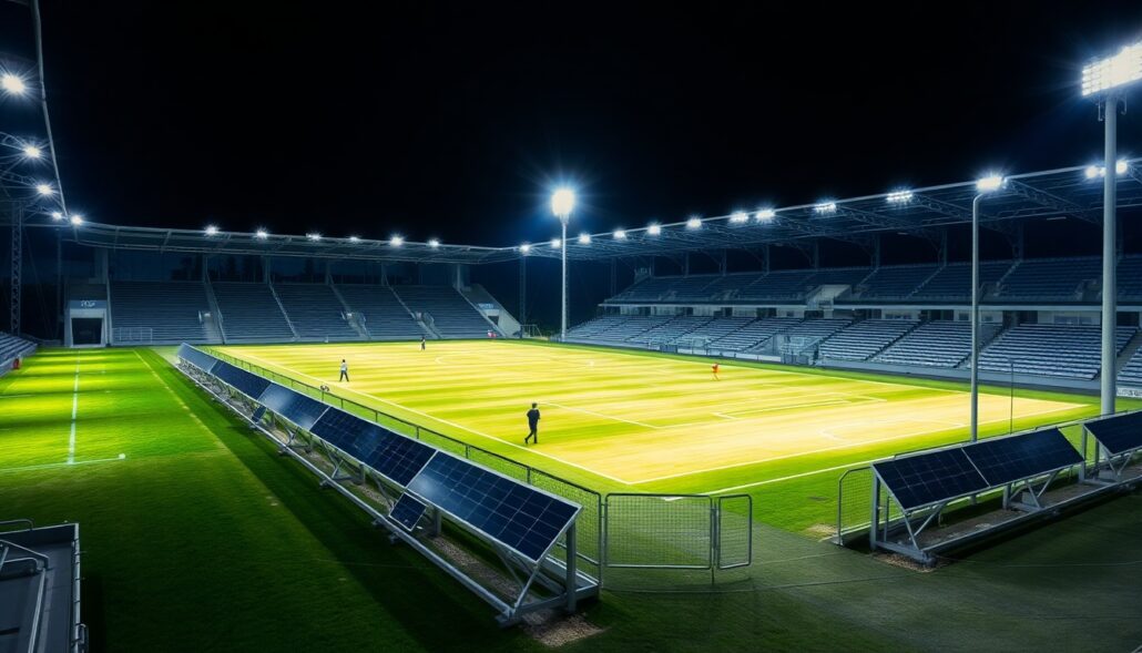
1. Overview and Design Objectives The lighting design for sports venues is a complex system engineering task that must meet
コンポーネントの比較と仕様 以下のデータは、両クラスの照明資産の標準的なハードウェア構成を特徴付けるものであり、以下のような特徴を示している。

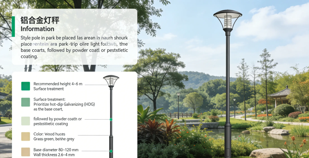
アルミ製旗竿を選ぶ際には、様々な高さや用途に応じた独自の要件を理解することが重要です。住宅用から装飾用まで、6フィートの旗竿から

Luxmanは、アルミ製伸縮式旗竿のトップメーカーであり、住宅用からオフィス用まで、さまざまな用途に最適な耐久性と軽量のソリューションを提供しています。
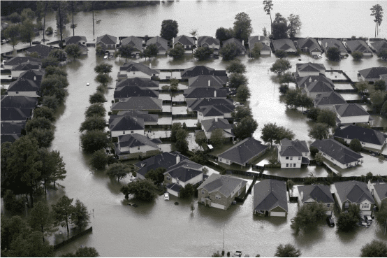
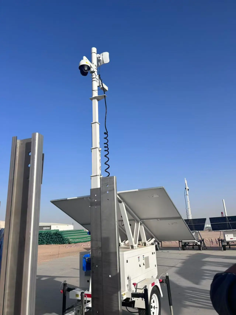
電力網が崩壊した被災地では、太陽光照明は捜索救助、医療支援、そして地域社会の安定のための生命線となります。

1. アルミ製旗竿の概要 定義と利点 アルミ製旗竿は、一般的に押し出し/溶接されたアルミニウム合金または
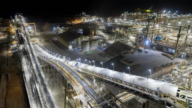
1. サウジアラビアにおける太陽光灯塔の背景と意義 暑く乾燥した気候、砂埃が多く、
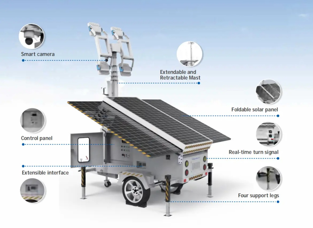
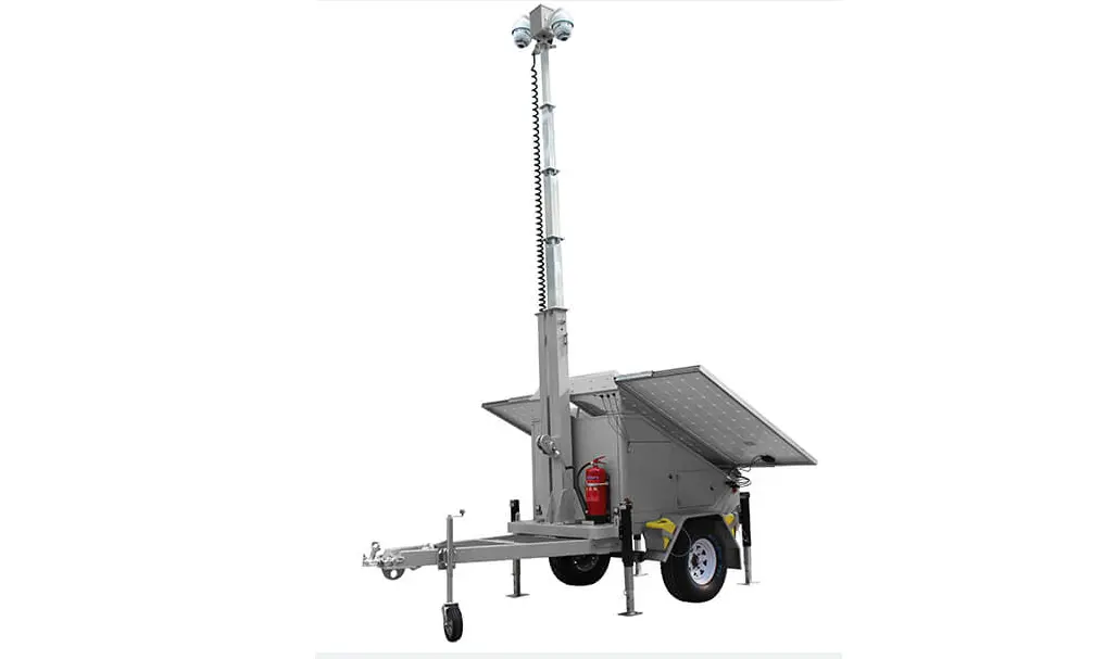
ライトタワーの定義と動作原理は何ですか?コンセプトと機能:ライトタワーは統合された高レベルの照明システムであり、