1. はじめに
屋外照明設計は、単純な空間照明の域をはるかに超える複雑な分野であり、公共の安全、視覚的快適性、エネルギー消費、そして自然環境に深く影響を及ぼします。これらの多面的な目標を達成するには、光を正確に制御し、分配することが鍵となります。この記事では、主要な配光コンセプト、特にカットオフ照明器具(フルカットオフ、カットオフ、セミカットオフを含む)、非カットオフ照明器具、バットウィング配光を包括的に分析し、北米の街路照明の確立された規格(主に北米照明学会(IESNA)によって定義)と厳密に比較することを目的としています。各タイプの技術的な定義、特徴、および一般的な用途を分析することで、それぞれのタイプの違いと相乗効果を明らかにし、都市計画、土木工学、照明設計の専門家が持続可能で規格に準拠した高品質の屋外照明ソリューションを開発するための貴重な洞察を提供します。
2. フィクスチャーのカットオフ分類を理解する
照明器具のカットオフ分類は、水平面より上方へ放射される光の程度を定義し、光害、グレア、および光侵入を管理する上で重要な役割を果たします。これらの分類は、歴史的に照明工学協会(IES)によって定義されており、上方放射光を制御するための枠組みを提供しています。
2.1. フルカットオフフィクスチャ
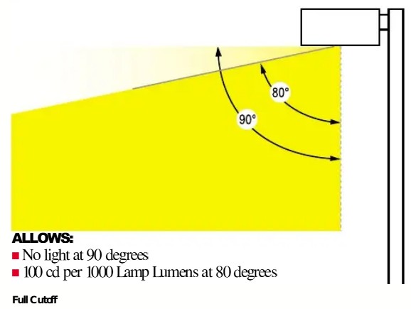
フルカットオフ照明器具の配光は、2つの厳格な基準によって定義されています。まず、90度以上の天底(真下)の光の強度(カンデラ)はゼロであり、照明器具が真上に光を放射しないことを示します。 1第二に、裸電球1000ルーメン当たりの垂直角度80度以上のカンデラ値が100を超えないこと(すなわち、10%) 1これらの制限は、器具の周囲のすべての横角に適用されます。
フルカットオフ器具は、すべての光を下向きに向けるように設計されており、スカイグロー(夜空の明るさ)と光の侵入(隣接する建物への不要な光の漏れ)を効果的に最小限に抑えます。 5この特性は、ダークスカイ規制の遵守と夜間環境の保全に重要な役割を果たします。さらに、高角度光を厳密に制御することで、直射日光のグレアを大幅に低減し、運転者と歩行者の視覚的快適性と安全性を向上させます。 6必要な場所にのみ光を正確に照射する効率性は、省エネにも役立ちます。 6そのため、北米の多くの地方規制や環境基準では、フルカットオフ器具の使用が義務付けられているか、強く推奨されています。 5.
2.2. カットオフフィクスチャ
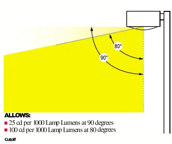
カットオフ照明器具の配光は、特定のカンデラ制限によって定義されます。垂直角度90度のカンデラ値は25(2.5%)を超えません。 2天底において、垂直角80度でのカンデラ値は100を超えない(10%) 2これらの制限はすべての横方向の角度に適用されます。90度を超える角度でも少量の光は許容されますが、カットオフ照明器具はセミカットオフ照明器具や非カットオフ照明器具と比較して上向きの光を大幅に制御するため、光害の軽減に役立ちます。
2.3. セミカットオフフィクスチャ
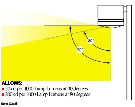
セミカットオフ照明器具は上向きの光に対する制限が緩く、垂直角度90度でのカンデラ値は50を超えません(5%)。 280度では、カンデラ値は200を超えません(20%) 2これらの制限は、すべての横方向の角度に適用されます。フルカットオフまたはカットオフ器具と比較して、セミカットオフ器具は高角度でより多くの光を放射するため、グレアやスカイグローが発生する可能性が高くなります。一般的に、環境的に敏感な地域や光害の厳格な制御が必要な状況には推奨されません。
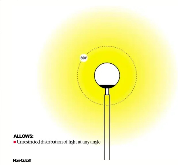
2.4. 非カットオフフィクスチャ
非カットオフ照明器具は、最大カンデラ領域を超える光強度(カンデラ)の制限がないことを特徴とする。 2これらの照明器具は、真上や水平方向を含むあらゆる方向に光を放射します。この制御不足は、深刻な光害(スカイグロー)を引き起こし、隣接する建物への光の侵入を招き、不快なグレアを引き起こすことがよくあります。 9環境問題への懸念の高まりと光害を抑制するための規制強化により、多くの管轄区域でその使用が制限または禁止されるようになっています。 6.
非カットオフ照明から完全カットオフ照明への進化は、屋外照明の悪影響を軽減することを目的とした照明工学と規制枠組みにおける思慮深い進歩を表しています。この傾向は、現代の照明デザインにおける環境への配慮と視覚的品質の向上の重要性の高まりを強調しています。非カットオフ照明の特徴である遮蔽されていない光は、グレア、隣接地への光漏れ、広範囲にわたる光害などの問題を引き起こします。 9逆に、フルカットオフのようなより厳しいカットオフ分類は、これらの問題に対処するために設計されており、「光害の軽減」、「スカイグローの最小化」、「グレアの軽減」、「視覚的快適性の向上」、「エネルギー効率の向上」を目的としています。 5この分類の進化は、業界や規制機関(国際ダークスカイ協会やIES RP-33など)が光害とグレアを重大な問題として認識し、より責任ある持続可能な照明慣行を促進するためのより厳格な基準を推進・確立してきたことに対する直接的な反応です。これは、照明設計が単なる照明の提供から、より広範な環境および人への影響を考慮した「高品質」な照明の提供へと移行したことを示しています。
従来のカットオフ分類システムがBUG(バックライト・アップライト・グレア)評価システムに置き換えられていることは注目に値する。 3この移行は、照明性能を評価するためのより詳細で包括的、かつ実用的なアプローチへの移行を示しており、上向きの光は光害と不法侵入の一要素に過ぎないことが認識されています。従来のカットオフシステムは、主に80°および90°を超える角度(上向きの光)での光の放射に焦点を当てています。しかし、BUG評価では、球面配光を「上向き」「前向き」「後ろ向き」の3つのゾーンに分割し、各ゾーンの光量を定量化します。 3つまり、アップライトだけでなく、後方への光の漏れ(逆光、不法侵入につながる)やグレア(前方に高い角度で放射され、不快感を引き起こす可能性のある光)も評価することになります。この変化は、アップライトの制御は重要ではあるものの、真に包括的で責任ある屋外照明を実現するには不十分であることを示しています。逆光は近隣の建物への重大な光の不法侵入につながる可能性があり、グレアは視覚的な快適さと安全に直接影響を及ぼします。BUG評価は、設計者と規制当局がすべての主要な光害と妨害に対処するための、より包括的で微妙な違いのあるフレームワークを提供します。これにより、照明器具のより正確な選択と設計が可能になり、単純な合否判定システムから段階的な多次元評価への移行を通じて、全体的な照明品質の向上、安全性の向上、環境管理の改善につながります。
表1: カットオフフィクスチャの分類特性の比較
分類タイプ | 90°におけるカンデラ限界(裸ランプ1000ルーメンあたり) | 80°におけるカンデラ限界(裸ランプ1000ルーメンあたり) | 主な機能 / アップライトコントロール | 関連する影響 |
フルカットオフ | 0 1 | 100を超えない(10%)1 | ゼロアップライト | 優れた暗い空への適合性、最小限のグレア、最小限の光害 |
切り落とす | 25を超えない(2.5%)2 | 100を超えない(10%)2 | 上向きの光がほとんどない | グレアコントロールが良好で、スカイグローが低減 |
セミカットオフ | 50を超えない(5%)2 | 200を超えない(20%)2 | 適度なアップライト | グレアや光の侵入の可能性 |
非カットオフ | 無制限2 | 無制限2 | アップライト制限なし | 光害やグレアのリスクが高い |
3. バットウィング・ディストリビューション
バットウィング配光は、照明エリア内の光質と均一性を最適化することを目的とした独自の光学設計戦略です。アップライトを制御するカットオフ分類や、面上の光の形状全体を定義するIESNAタイプとは異なり、バットウィング配光は照明の均一性に重点を置いています。
3.1. 定義と独自のプロファイル
バットウィング配光は、広いビーム角度範囲にわたって非常に均一な光出力を生成する能力を特徴としています。 12「バットウィング」という名前は、極座標グラフにプロットするとコウモリの翼に似た独特の光強度プロファイル形状に由来し、天底の両側に2つの強度ピークを示します。 12.
この独自の配光は、通常、特別に設計された拡散板や高度な光学部品を器具内に組み込むことで実現されます。これらの光学部品は、LED光源から発せられた光を、均一間隔の小さなビームに分解することで機能します。この巧妙な拡散プロセスにより、一般的な「ホットスポット」配光(中央が最も明るく、周辺に向かって急速に暗くなる)が、より均一な光出力へと変換されます。 12さらに、一部のバットウィングデザインでは、特定の照明ニーズを満たすために「二重角度曲げ光強度」を実現するために光学フィルムを使用しています。 13.
3.2. 利点と応用
バットウィング分布には、従来の光パターンに比べていくつかの大きな利点があります。
より均一な光出力:ビーム角度範囲全体にわたって照明レベルの一貫性を確保し、明るさの変化を最小限に抑え、暗いスポットの発生を減らします。 12.
ホットスポットの削減: 集中した光領域を排除することで、バットウィング分布は視覚的な不快感を軽減し、より美的に心地よい照明環境を作り出します。 12.
視覚的快適性とグレアフリー環境の改善:均一な光の分布により、強いコントラストと直射グレアが大幅に軽減され、より快適で人間工学的な視覚体験をユーザーに提供します。 12.
生産性と気分の向上: 研究によると、快適でグレアのない均一な照明環境は、オフィス、小売スペース、教室、図書館など、さまざまな環境でユーザーの生産性と全体的な幸福にプラスの影響を与える可能性があります。 12.
バットウィング配光は、均一でグレアのない条件を必要とする幅広いアプリケーションに最適です。
商業および工業スペース: オフィス、小売環境、教室、図書館では、影やホットスポットのない照明により、集中力が向上し、目の疲れが軽減されます。 12.
住宅照明: 家庭内のより快適で暖かい雰囲気を作り出すのに役立ちます。
間接照明:吊り下げ式の間接照明器具と組み合わせると特に効果的です。光は天井に向けられ、間接的に空間を照らします。これにより、反射光のパターンが広く均一になり、均一性がさらに高まり、直射日光の眩しさを軽減します。 12.
バットウィング配光は、カットオフや IESNA タイプのような独立した分類システムではなく、器具に組み込むことができる光学設計機能です。これは、照明エリア内の光の品質と均一性に焦点を当てており、より広範な分類システムを補完する機能として機能します。この区別は重要です。バットウィングは IESNA またはカットオフ分類の代替ではなく、特定のカットオフおよび IESNA 要件を満たす器具に組み込むことができる高度な光学エンジニアリング ソリューションです。たとえば、駐車場用に設計されたフル カットオフ器具 (IESNA タイプ V など) は、バットウィング光学素子を使用して、不快なホットスポットのない、エリア全体に均一に明るい円形の光パターンを確保できます。これは、効果的な照明設計には、漏れ光の制御 (カットオフ)、照明エリアの形状設定 (IESNA)、およびそのエリア内の光品質の最適化 (バットウィング) という、複数の重なり合う考慮事項が含まれることを強調しています。
バットウィング配光の開発と採用は、単なる量的な照明(例えば、一定の照度レベルを達成すること)を超え、視覚的な快適さや全体的なユーザーエクスペリエンスといった照明の質的な側面を優先する設計哲学を反映しています。これは、人間工学が技術仕様にますます統合されるようになった照明設計の成熟を示しています。従来の照明設計は、主に最低照度の達成に重点を置いていました。しかし、「ホットスポット」と「グレア」は、「不快感と疲労」、「視覚的緊張」、そして「居心地の悪い」環境の創出につながる問題として認識されています。バットウィングの利点(均一性、グレアの低減、生産性の向上)は、これらの質的な欠陥に直接対処します。 12これは照明デザインにおける優先順位の変化を示しています。定量的な照度レベルを満たすことは依然として重要ですが、光の分布の「質」、つまりいかに均一かつ快適に光が届けられるかが、人間の健康、作業パフォーマンス、そして照明空間における全体的な満足度にとって同様に重要であるという認識が高まっています。これは、照明デザインに対するより包括的で人間中心のアプローチを表しています。
4. 北米街路照明基準:IESNA分類
北米照明学会(IESNA)は、水平面における光の分布を規定する基本的な分類システムを開発しました。これは、北米全域の道路、駐車場、その他の屋外エリアの設計において非常に重要です。このシステムは、照明器具の性能を記述するための標準化された言語を提供します。
4.1. IESNA分類システムの概要
IESNA分類システムは、主に照明器具によって生成される照明領域の形状と範囲に基づいています。 8道路、歩道、駐車場など、さまざまな屋外照明システムの設計と設置に不可欠なガイドラインを提供します。 8この分類は、標準化されたグリッド上で光が最も多く当たる場所を測定することで配光を決定します。特に、最も高いカンデラ強度(光強度分布)の点に着目します。このシステムは、横方向の配光(道路を横切る)と縦方向の配光(道路方向に沿った)の両方を考慮します。 8.
北米における道路および駐車場の照明に関する包括的な規格は、ANSI/IES RP-8(道路および駐車場の照明に関する推奨基準)です。この規格は、IESが過去に制定した多数の独立した規格をまとめたもので、道路や歩行者用の様々な用途における設計、保守、エネルギー効率、環境への影響、安全性に関する詳細なガイダンスを提供しています。 11.
4.2. 側面配光タイプ(タイプI、II、III、IV、V、VS)
これらの分類は、道路や照明エリアに沿って光がどのように横方向に分布するかを定義し、器具が光強度の50%に達するポイントによって特徴付けられます。 8.
タイプI:
特徴:狭角な対称または非対称の楕円形の光パターンを照射します。通常、メインビーム角は約15度です。50%のカンデラ光軌跡は、住宅側の設置高さ(MH)と道路側の設置高さ(MH)の間にあります。 8.
用途: 歩道、狭い通路、境界照明、片側一車線道路などの狭く細長いエリアに最適です。 8.

タイプII:
特徴:25度の横方向の優先照射角を持つ、狭幅の非対称パターンを特徴としています。50%のカンデラの軌跡は、道路側の設置高さの1倍から設置高さの1.75倍までの範囲となります。 8このタイプは、通常、比較的狭い道路の手前側または近くに設置され、幅が設計設置高さの1.75倍を超えない器具に適しています。 9.
用途: 1~2車線道路、主要通路、高速道路、広い歩道、小さな脇道、ジョギングコース、自転車レーンに適しています。 8.
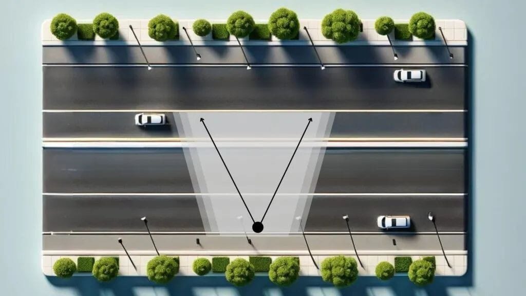
タイプIII:
特徴:左右40度の広い非対称パターンを照射し、外側と側面に光を照射するように設計されています。50%のカンデラの軌跡は、設置高さの1.75倍から2.75倍の範囲にあります。 8このタイプは、通常、照明エリアの側面に設置され、照明エリアの幅は通常、ポールの高さの2.75倍未満である必要があります。 16.
用途: 主要な通路、高速道路、駐車場、広い範囲をカバーする必要がある大きなオープンエリアでよく使用されます。 8.
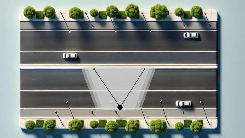
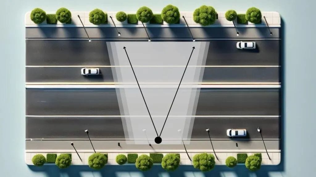
タイプIV:
特徴:非対称の前方投光パターンを有し、横方向の照射角は60度を推奨します。90度から270度の範囲に強力で均一な照明を提供します。50%のカンデラの照射範囲は、設置高さの2.75倍から3.75倍の範囲です。 8楕円形の光パターンを放射し、タイプIIIよりも狭い幅で前方に照射するため、光漏れを効果的に抑制します。 8幅員が設置高さの3.7倍を超えない広い道路の側方に取り付けるように設計されています。 9.
用途: 駐車場、広場、建物の外壁など、主に前方に光を照射し、後方への漏れを厳密に制御する必要がある壁や柱への取り付けが必要な周辺用途に最適です。 8半円形の光を発する 21.
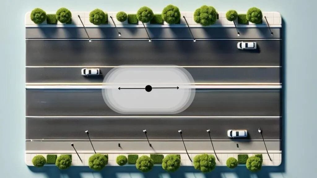
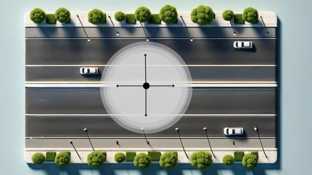
タイプV:
特徴: すべての横角で均等な強度を持つ完全に対称的な円形の光パターンを生成します 450%カンデラの軌跡は、器具の周りで円対称です。 8.
用途: 駐車場、交差点、公園、一般的な作業エリアや作業エリアなど、あらゆる方向に均一に光を照射する必要がある広いオープンエリアを中央の取り付け点から照らすのに最適です。 4.
タイプVS:
特徴: タイプVに似ていますが、すべての横角で一貫した強度を持つ対称的な正方形の光パターンを生成します。 4.
用途: 駐車場や公共広場など、均一な正方形の照明を必要とする広いエリアに適しています。 9.
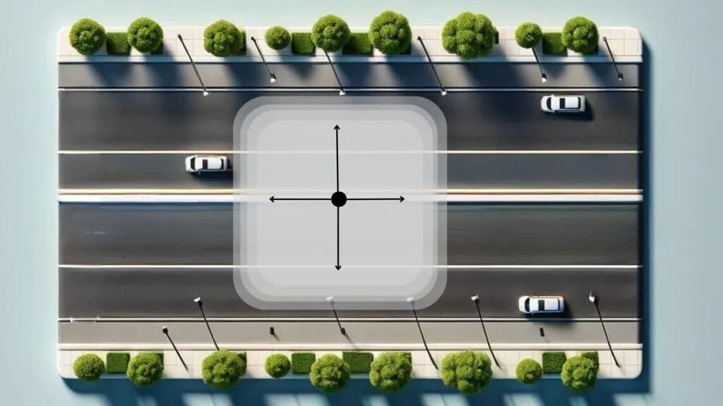
表2: IESNA横方向配光タイプ(IV/VS)
IESNAタイプ | 半最大カンデラ点範囲(MH、道路側/家屋側) | 推奨横幅(度、該当する場合) | 一般的な配光パターン | 主な用途 |
タイプI | 家側の1MHから道路側の1MHへ 8 | 約15 15 | 狭い対称または非対称 | 歩道、狭い道、片側一車線道路 |
タイプII | 1MH の道路側から 1.75MH 8 | 25 21 | 狭く非対称な | 1~2車線の道路、広い歩道、自転車レーン |
タイプIII | 1.75 MHから2.75 MH 8 | 40 16 | ワイドアシンメトリー | 主要道路、高速道路、駐車場 |
タイプIV | 2.75 MHから3.75 MH 8 | 60 9 | 非対称前方投げ | 壁面設置、駐車場周辺、広場 |
タイプV | 器具の周りで円対称 8 | 特定の角度はなく、360°対称 21 | 円形対称 | 駐車場、交差点、広いオープンスペース |
タイプVS | すべての横角で基本的に同じ 14 | 特定の角度はなく、360°対称 4 | 正方形対称 | 大きな広場、駐車場 |
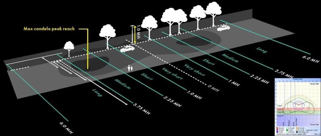
4.3. 垂直配光タイプ(極短、短、中、長、極長)
これらの分類は、最大カンデラ点の位置に基づいて、道路に沿って光がどのように垂直に分布するかを定義します。 8これらは、適切なポール間隔を決定し、道路沿いの均一な照明を確保するために重要です。
非常に短い(VS):最大カンデラポイントは、道路沿いの設置高さの0~1.0倍の間になります。 8推奨ポール間隔は設置高さの約1倍です。 14.
短距離(S):最大カンデラポイントは、道路沿いの設置高さの1.0~2.25倍の範囲になります。 8「S」分類の器具は、通常、ポール間隔が設置高さの2.25倍未満の状況に適しています。 8.
中(M):最大カンデラポイントは設置高さの2.25~3.75倍の範囲になります。 8このタイプは、ポール間隔が設置高さの2.25~3.75倍の場合に適しています。 8.
ロング(L):最大カンデラポイントは設置高さの3.75~6.0倍の範囲になります。 8「L」分類の器具は、設置高さの3.75~6.0倍の広いポール間隔に適しています。 8.
非常に長い(VL):最大カンデラポイントが設置高さの6.0倍を超える 8.
表3: IESNA垂直配光タイプ(VS、S、M、L、VL)
IESNA垂直タイプ | 最大カンデラポイント範囲(MHの道路方向に沿って) | 推奨ポール間隔(MH) | 主な用途/影響 |
非常に短い(VS) | 0 - 1.0 8 | 1 14 | 非常に狭いポール間隔 |
ショート(S) | 1.0 - 2.25 8 | 1.0 - 2.25 14 | ポール間隔が狭い |
ミディアム(M) | 2.25 - 3.75 8 | 2.25 - 3.75 14 | 中程度のポール間隔 |
ロング(L) | 3.75 - 6.0 8 | 3.75 - 6.0 14 | ポール間隔の拡大 |
非常に長い(VL) | > 6.0 8 | > 6.0 | 非常に広いポール間隔 |
IESNA分類は基礎的なものです。しかし、厳格な規則というよりはガイドラインとしての役割を担っています。効果的な適用には、設置場所特有の様々な要因を考慮する必要があり、最適な照明を実現するには、高度な照明設計ツールと専門家の判断が極めて重要であることが強調されます。多くの資料では、IESNA分類は「ガイドライン」または「固定ルールではない」ものであり、「器具の取り付け高さ、傾斜角度、アームの長さ、器具と縁石の距離」、さらには「器具のレイアウトと道路状況」などの要因によって影響を受けると明記されています。 8文書では、配光を最適化する上での「測光データ」と「モデリング」の重要性についても言及している。 15IESNAタイプによって定義された理論的な配光は、設置パラメータによって大きく変化する可能性があります。例えば、取り付け高さや傾斜角度が不適切だと、「正しい」IESNAタイプを選択したとしても、均一性が不十分になったり、グレアが過剰になったり、配光が非効率になったりする可能性があります。こうした複雑さから、詳細な測光分析とモデリングが求められ、効果的な照明設計は反復的で複雑なプロセスであることがわかります。単にカタログから器具タイプを選択するだけでは不十分です。設計者は、理論的な知識(IESNA規格)と実際の現場条件を統合し、高度なモデリングツールを用いて選択を検証する必要があります。これは、これらの複雑な状況を乗り越え、真に最適化された高性能な照明ソリューションを提供するためには、照明の専門家が果たす役割の重要性を強調するものです。
IESNAシステムは、横方向と垂直方向の配光を包括的に分類することで、照明範囲とポール間隔を最適化するための強固な枠組みを提供します。この二重の分類は、道路照明プロジェクトにおけるエネルギー効率と安全性の向上に直接貢献します。IESNAは、光を「横方向」(道路を横断する方向、道路幅と照明範囲に関連)と「垂直方向」(道路方向、ポール間隔に関連)の分布に基づいて分類します。 8横型(IV/VS)は道路幅に合わせて設計されています(例:片側車線用はタイプI、両側車線用はタイプII、高速道路用はタイプIII、広域照明用はタイプV)。縦型(S、M、L)は「推奨ポール間隔」および「ポール高さ」に直接対応しています。 8IESNAは、道路に沿って光がどのように横方向および垂直方向に伝播するかを正確に定義することで、設計者が光の重なり(エネルギーの無駄)を最小限に抑え、暗い部分(安全性と視覚的快適性への影響)を排除する器具を選択できるようにします。例えば、「長い」垂直分布を選択すると、ポール間隔を広げることができ、特定のセグメントに必要なポールと器具の数を大幅に削減できます。これは、初期設置コストと長期的なエネルギー消費に直接影響します。 8逆に、垂直方向の配光を誤ると、照明が過剰になったり、ポール間の照度が不足したりする可能性があります。水平方向と垂直方向の分類を統合することで、機能的に効果的で資源効率の高い、高度に最適化された照明設計が可能になります。この最適化は、ANSI/IES RP-8-22などの規格に概説されている目標、すなわち「エネルギー消費の最小化」、「運転者の視認性の向上」、「高品質な照明の提供と危険物の視認性コントラストの向上」を達成するために不可欠です。 18これは、照明のニーズと経済的実現可能性、安全性、環境への影響とのバランスをとることを目的とした体系的かつ科学的なアプローチを表しています。
5. 比較分析と設計上の考慮事項
北米における効果的な屋外照明設計は、様々な分類システムと光学特性の複雑な相互作用を反映しています。カットオフ照明器具、非カットオフ照明器具、バットウィング分布、そしてIESNA分類がどのように相互作用するかを理解することは、最適で規制に準拠した持続可能な照明ソリューションを開発する上で不可欠です。
5.1. カットオフ分類とIESNAタイプの相互作用
カットオフの分類(完全カットオフ、カットオフ、セミカットオフ、非カットオフ)は、主に水平面より上に放射される光の量を制御し、光害やグレアを制御するための重要なメカニズムとして機能します。 1対照的に、IESNAタイプ(IV / VS)は、地上の光の形状と分布を記述し、道路や駐車場などのエリアの照明の有効性を決定します。 8.
現代の北米の街路照明では、フルカットオフ照明器具の使用が圧倒的に重視されています。これは、厳格なダークスカイ対策、環境保護目標、そして光の侵入とグレアを最小限に抑えたいという願望によって推進されています。 5これらのフルカットオフ照明器具は、IESNA規格の横方向および垂直方向の配光特性に基づいて設計されます(例:フルカットオフタイプIII中配光照明器具)。「カットオフ」は光の上方向への漏れを防ぐことで環境への配慮を確保し、「IESNAタイプ」は光を機能的に方向付け、対象エリア(例:複数車線の高速道路や大型駐車場)に配光します。これら2つのシステムは相乗的に機能します。カットオフは「光が届かない場所」を、IESNAは「光が届く場所と配光方法」を規定します。
5.2. Batwing分布とIESNA分類の統合
バットウィング配光自体はIESNA分類でもカットオフ分類でもありません。むしろ、照明領域内の光の「質」と「均一性」を高めることを目的とした特殊な光学設計上の特徴です。 12その主な目的は、ホットスポットを排除し、グレアのない快適な照明環境を提供することです。
バットウィング光学素子は、IESNAの様々な配光特性を持つ照明器具、特に広範囲をカバーするように設計された照明器具にシームレスに組み込むことができます。例えば、対称的な円形パターン(IESNAタイプV)を形成する照明器具には、バットウィング光学素子を装備することができます。 9この組み合わせにより、対称的であるだけでなく、不快なホットスポットのない非常に均一な円形の光パターンが作成され、大きな広場、中央の交差点、またはオープンな工業用スペースなど、一貫した照明が必要なエリアに最適です。 9同様に、タイプIII分布にも見られる。 23これは、バットウィングがIESNAの量的フレームワーク内で質的強化として機能する方法を示しています。
5.3. 北米の街灯プロジェクトに関する包括的な考慮事項
北米の街路灯プロジェクトにおける照明器具の選定は、規制遵守(カットオフ/BUG)、機能要件(IESNA水平/垂直)、そして光質(バットウィング、グレア制御)のバランスを取りながら総合的なアプローチを必要とする多次元最適化問題であり、最適な安全性、効率性、そして環境管理を実現します。これは、単独の、孤立した選択であることはほとんどありません。
エネルギー効率:適切なカットオフ分類(特にフルカットオフ)と最適化されたIESNAタイプを備えた照明器具を戦略的に選択することは、エネルギー節約に直接貢献します。必要なエリアに正確に光を当て、無駄な光(アップライト、バックライト、スピルオーバー)を最小限に抑えることで、全体的なエネルギー消費を削減できます。 6LED技術の普及により、その固有の設計柔軟性と高いルーメン/ワット出力により、これらの効率はさらに向上します。 9.
視覚的な快適性と安全性:グレアを最小限に抑え、高い照明均一性を確保することは、視覚的な快適性と安全性にとって不可欠です。適切なカットオフ照明器具は、運転者や歩行者にとって不快なグレアを軽減します。また、適切なIESNAタイプ(バットウィング光学素子の導入によりさらに強化可能)は、均一な光量を確保し、影を減らし、危険箇所の視認性を向上させます。 8これは夜間の車両事故率の低下と歩行者の安全性の向上に直接関係している。 18.
ダークスカイの取り組みと環境への影響:完全な遮断の原則と、ダークスカイ・インターナショナルなどの組織のガイドラインを遵守する 7 IES推奨基準(RP-33屋外環境照明推奨基準など) 5 夜空の輝きを緩和し、自然の夜景を保護し、夜行性の生態系を保護するために不可欠です。これは、照明デザインにおける環境意識の高まりを反映しています。
規制遵守: 北米全域の地方規制、市町村条例、州法では、特定のカットオフ分類(例:フルカットオフ)が義務付けられていることが多く、一般的にさまざまな屋外照明アプリケーションがIESNAタイプに準拠することを推奨または要求しています。 5コンプライアンスは法的要件であるだけでなく、責任ある都市開発への取り組みでもあります。
経済的メリット:環境面および安全面の利点に加え、IESNA規格およびカットオフ要件に準拠した最適化された照明設計は、大きな経済的メリットをもたらします。これには、初期設置コストの削減(例えば、IESNA垂直型照明器具のポール間隔の最適化など)が含まれます。 8)およびエネルギー節約による長期的な運用コストの削減 18さらに、明るい場所は人々の認識を高め、商業地区への歩行者の増加を促し、経済活動を活性化させる可能性がある。 18.
実際の用途では、照明器具は複数の要件を満たす必要があります。たとえば、暗い空の規制に準拠し、光害を最小限に抑えるためには、「完全にカットオフ」する必要があります。 6特定の幅の道路を効果的に照らすために、適切なIESNA横型(例えば、タイプIIまたはタイプIII)を備えている必要があります。 8道路沿いのポール間隔を最適化し、均一性と費用対効果を確保するために、適切なIESNA垂直タイプ(中型または長型など)を使用する必要があります。 8;また、表面の光がぎらつきなく均等に分散され、ユーザーの視覚的快適性を高めるために、バットウィング光学素子を組み込む必要があるかもしれない。 12さらに、すべてのデザインは地方自治体の条例に準拠する必要があります。 5この多面的な要件は、照明設計者がIESNA規格の1つのタイプだけを単純に切り離すことはできないことを示しています。照明器具のカットオフ定格、内部の光学要素(バットウィングなど)、そしてこれらの特性がプロジェクトの様々な機能的、環境的、規制的、そして美的目標を満たすためにどのように連携するかを考慮する必要があります。これらの基準をすべて同時に満たす照明器具を見つけるのは複雑であり、多くの場合、詳細な測光分析とモデリングツールが必要になります。 15これは、現代の屋外照明において専門家のコンサルティングと包括的な設計プロセスが果たす重要な役割を浮き彫りにしています。
6. 結論
屋外照明設計、特に北米においては、様々な配光コンセプトへの深い理解を核とする、複雑で繊細な分野です。本稿では、カットオフ照明器具(フルカットオフ、カットオフ、セミカットオフ)、非カットオフ照明器具、そして特殊バットウィング配光といった照明器具の基本的な違いを解説し、道路照明に関する権威あるIESNA分類システムとの包括的な比較を行います。
カットオフ分類は、主に光害やグレアを抑制するための重要なメカニズムとして機能します。フルカットオフ照明器具は、すべての光を下向きに照射することで、最も厳格かつ環境に優しい基準を満たしています。一方、非カットオフ照明器具は、こうした制御がないため、光の侵入やスカイグロー(光の反射)が大幅に増加し、その使用はますます制限されています。バットウィング配光は、これらのより広範な分類とは異なり、照明エリア内で優れた均一性と視覚的快適性を実現することに重点を置いた光学工学的ソリューションであり、通常はホットスポットのない照明を必要とする特定の用途において、IESNAタイプの補足として使用されます。
結局のところ、北米における最良の街路照明設計は、複雑かつ包括的な作業です。IESNA(国際照明協会)が規定する精密なエリアベースの配光パターンを、厳格なカットオフ要件と統合し、必要に応じてバットウィング配光などの高度な光学ソリューションも導入する必要があります。この統合アプローチは、機能的な照明を確保するだけでなく、エネルギー効率を最大化し、公共の安全と視覚的快適性を高め、重要なダークスカイ保護対策を維持します。これらの統合された基準と考慮事項に基づいて、情報に基づいた器具の選定と専門的な設計を導くことは、地域社会にとって持続可能で、規制に準拠した、高品質な屋外照明環境を創出するために不可欠です。